基于STC89C52RC单片机的大棚温湿度自动控制系统毕业论文+外文翻译及原文+C程序+proteus仿真文件+Altium Designer原理图
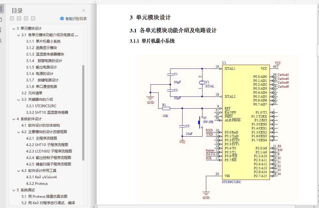
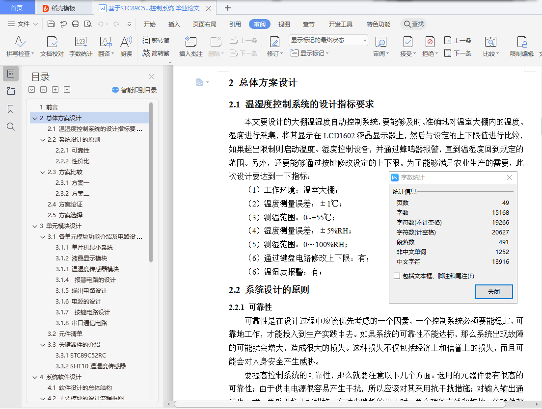
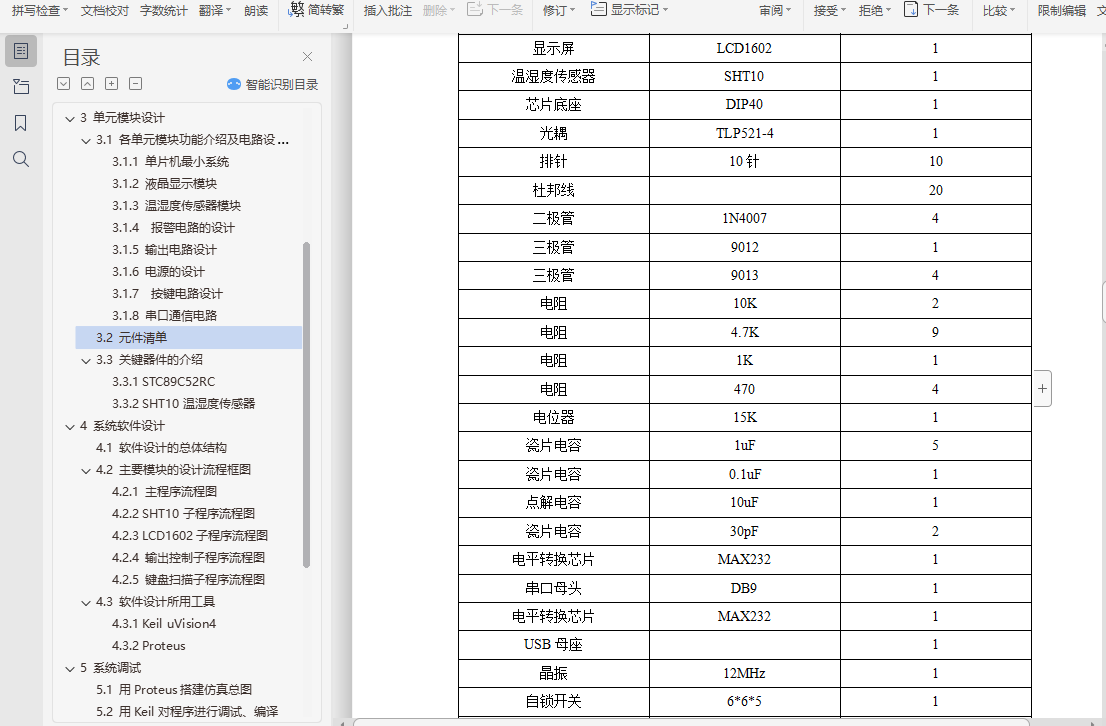
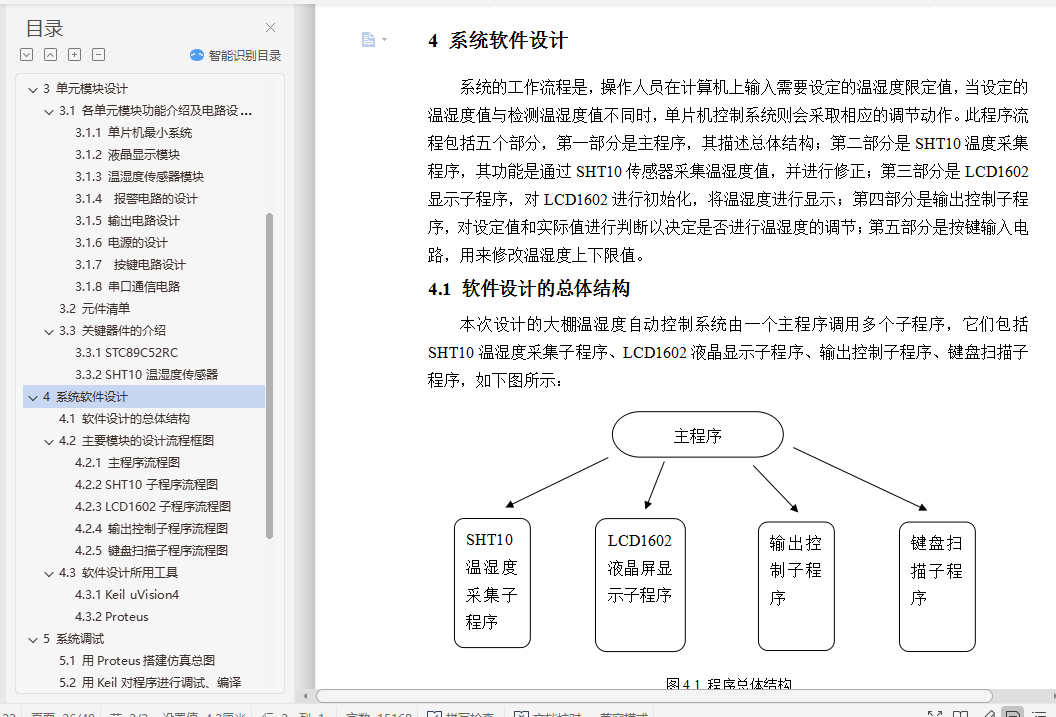
大棚温湿度自动控制系统设计摘 要:本设计是基于STC89C52RC单片机的大棚温湿度自动控制系统,采用SHT10作为温湿度传感器,LCD1602液晶屏进行显示。SHT10使用类似于I2C总线的时序与单片机进行通信,由于它高度集成,已经包括A/D转换电路,所以使用方便,而且准确、耐用。LCD1602能够分两行显示数据,第一行显示温度,第二行显示湿度。这个控制系统能够测量温室大棚中的温度和湿度,将其显示在液晶屏LCD1602上,同时将其与设定值进行对比,如果超出上下限,将进行报警并启动温湿度调节设备。此外,还可以通过独立式键盘对设定的温湿度进行修改。通过设计系统原理图、用Proteus软件进行仿真,证明了该系统的可行性。关键词:STC89C52RC,SHT10,I2C总线,独立式键盘,温湿度自动控制Abstract: This design is an automatic temperature and humidity controller for greenhouses, with the STC89C52RC MCU being its main controller. It uses the SHT10 as the temperature and humidity sensor, and the LCD1602 to display the messages. The SHT10 uses a timing sequence much like the I2C to communicate with the micro-controller. Because it’s a highly integrated chip, it already includes an analog to digital converter. Therefore, it’s quite convenient to use, and also accurate and durable. The LCD1602 can display two lines of messages, with the first line for temperature and the second line for humidity. The design can measure the temperature and humidity in a greenhouse, and then display it on a LCD1602. Meanwhile, it compares the data with the set limit. If the limit is exceeded, then the system will send out a warning using a buzzer and activate the temperature and humidity controlling equipment. Besides, the set limit can be modified with the independent keyboard. Through schematic design and Proteus simulation, the feasibility of this design has been proved.Keywords: STC89C52RC, SHT10, I2C bus, independent keyboard, temperature and humidity control目 录1 前言 12 总体方案设计 32.1 温湿度控制系统的设计指标要求 32.2 系统设计的原则 32.2.1 可靠性 32.2.2 性价比 32.3 方案比较 42.3.1 方案一 42.3.2 方案二 42.4 方案论证 52.5 方案选择 53 单元模块设计 63.1 各单元模块功能介绍及电路设计 63.1.1 单片机最小系统 63.1.2 液晶显示模块 83.1.3 温湿度传感器模块 83.1.4 报警电路的设计 93.1.5 输出电路设计 103.1.6 电源的设计 123.1.7 按键电路设计 133.1.8 串口通信电路 143.2 元件清单 153.3 关键器件的介绍 173.3.1 STC89C52RC 173.3.2 SHT10温湿度传感器 194 系统软件设计 224.1 软件设计的总体结构 224.2 主要模块的设计流程框图 244.2.1 主程序流程图 244.2.2 SHT10子程序流程图 254.2.3 LCD1602子程序流程图 274.2.4 输出控制子程序流程图 284.2.5 键盘扫描子程序流程图 294.3 软件设计所用工具 314.3.1 Keil uVision4 314.3.2 Proteus 315 系统调试 325.1 用Proteus搭建仿真总图 325.2 用Keil对程序进行调试、编译 336 结论 366.1 系统的功能 366.2 系统的指标参数 366.3 系统功能分析 367 总结与体会 388 致谢 399 参考文献 40附录1 系统的电路原理图 41附录2 系统仿真总图 42附录3 系统实物照片 43附录4 系统源程序 44