 |
 |
| 首页 | 机械毕业设计 | 电子电气毕业设计 | 计算机毕业设计 | 土木工程毕业设计 | 视觉传达毕业设计 | 理工论文 | 文科论文 | 毕设资料 | 帮助中心 |
| 今天是: |
|>>> 您现在的位置:首页>>>>文档详细内容 |
| 设计 任务书 文档 开题 答辩 说明书 格式 模板 外文 翻译 范文 资料 作品 文献 课程 实习 指导 调研 下载 网络教育 计算机 网站 网页 小程序 商城 购物 订餐 电影 安卓 Android Html Html5 SSM SSH Python 爬虫 大数据 管理系统 图书 校园网 考试 选题 网络安全 推荐系统 机械 模具 夹具 自动化 数控 车床 汽车 故障 诊断 电机 建模 机械手 去壳机 千斤顶 变速器 减速器 图纸 电气 变电站 电子 Stm32 单片机 物联网 监控 密码锁 Plc 组态 控制 智能 Matlab 土木 建筑 结构 框架 教学楼 住宅楼 造价 施工 办公楼 给水 排水 桥梁 刚构桥 水利 重力坝 水库 采矿 环境 化工 固废 工厂 视觉传达 室内设计 产品设计 电子商务 物流 盈利 案例 分析 评估 报告 营销 报销 会计 | |||||
|
|||||
|
|||||
|
|||||
随着汽车大量涌入人们的生活中,人们对汽车的安全性、舒适性、经济性等各个方面性能的要求不断提高,使得电子控制单元(ECU)的控制功能越来越复杂。传统的测试必须等汽车样机开发出来之后才能进行实车测试,这样的流程容错率低、流程繁琐,且极端测试非常危险,给 ECU 的开发测试带来了困难。而
HIL 仿真测试可重现与 ECU 交互的物理系统,为 ECU 软件算法及硬件功能的测试和验证提供了良好的环境,提高测试效率,增加测试覆盖率和灵活性,以及降低测试成本。本文以硬件在环测试的思想为基础,自主研发硬件在环仿真测试系统,并进行了 ECU 的功能测试。
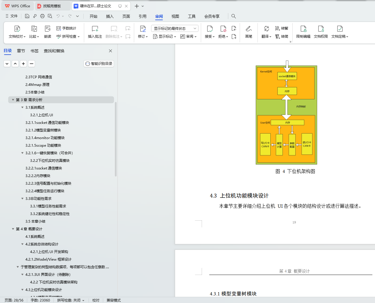
本文设计并实现了一个硬件在环仿真测试系统。系统的主要功能是实现对现有的 ECU 的功能和控制算法进行测试。系统主要包括三个核心部分:上位机监控软件、下位机实时仿真平台以及 IO 接口。其中上位机监控软件基于 Qt 实现,主要功能在于为用户提供监控和测试命令的可视化界面。下位机实时仿真平台分为内核空间和用户空间,内核空间用于模型任务的调度,IO 板卡的驱动实现,用于保证实时性;用户空间主要是运行模型任务,与上位机进行数据通信,以及以
IO 接口之间进行数据交换。IO 接口部分介于 ECU 与模型之间,提供与被测部件交互的模拟、数字和总线信号。
本文详细介绍了本硬件在环仿真测试系统的概要设计、详细设计与实现以及系统测试。目前,本系统的各个环节均已打通,整个系统的三大核心部分均已实现。测试人员可以在上位机监控软件对待测 ECU 进行基本的功能测试。为后续持续的开发打下坚实的基础。
关键词:电子控制单元;HIL 测试;实时性;IO 接口
With the influx of automobiles into people's lives, people's requirements for the safety, comfort, economy and other aspects of automobiles are constantly increasing, making the control functions of the electronic control unit (ECU) more and more complicated. The traditional test must wait for the development of the car prototype before the actual vehicle test can be carried out. Such a process has a low fault tolerance rate, a cumbersome process, and extreme testing is very dangerous, which brings difficulties to the development and testing of ECU. The HIL simulation test can reproduce the physical system that interacts with the ECU, providing a good environment for the testing and verification of ECU software algorithms and hardware functions, improving test efficiency, increasing test coverage and flexibility, and reducing test costs. Based on the idea of hardware-in-the-loop testing, this paper independently develops a hardware-in-the-loop simulation test system and conducts ECU functional testing.
This paper designs and implements a hardware-in-the-loop simulation test system. The main function of the system is to test the functions and control algorithms of the existing ECU. The system mainly includes three core parts: upper computer monitoring software, lower computer real-time simulation platform and IO interface. The host computer monitoring software is implemented based on Qt, and its main function is to provide users with a visual interface for monitoring and testing commands. The real-time simulation platform of the lower computer is divided into kernel space and user space. The kernel space is used for the scheduling of model tasks, and the driver implementation of the IO board is used to ensure real-time performance; the user space is mainly for running model tasks and communicating data with the upper computer. And to exchange data between IO interfaces. The IO interface part is between the ECU and the model, providing analog, digital and bus signals that interact with the component under test.
This article introduces in detail the outline design, detailed design and implementation, and system testing of the hardware-in-the-loop simulation test system. At present, all links of the system have been opened up, and the three
core parts of the entire system have been realized. Testers can perform basic functional tests on the ECU to be tested in the host computer monitoring software. Lay a solid foundation for subsequent continuous development.
Key Words: electronic control unit; HIL test; real-time; IO interface
目 录
目录
摘 要I
ABSTRACTII
第 1 章 绪论1
1.1选题背景及研究意义 1
1.2国内外研究现状 2
1.2.1国外研究现状 2
1.2.2国内研究现状 3
1.3本文的主要工作 3
1.4本文的组织结构 4
第 2 章 相关技术简介5
2.1硬件在环 5
2.2MODEL/VIEW 框架 6
2.3TCP 网络通信 6
2.4MMAP 原理 8
2.5本章小结 11
第 3 章 需求分析12
3.1系统概述 12
3.2功能性需求 (下可合并) 12
3.2.1上位机 UI 12
3.2.2下位机实时仿真模块 14
3.3非功能性需求 15
3.3.1模型任务性能需求 15
3.3.2系统健壮性和稳定性 15
3.5 本章小结 16
第 4 章 概要设计17
4.1系统概述 17
4.2系统总体结构设计 17
4.2.1上位机 UI 开发架构 18
4.2.2下位机实时仿真模块架构 19
4.3上位机功能模块设计 19
4.3.1模型变量树模块 20
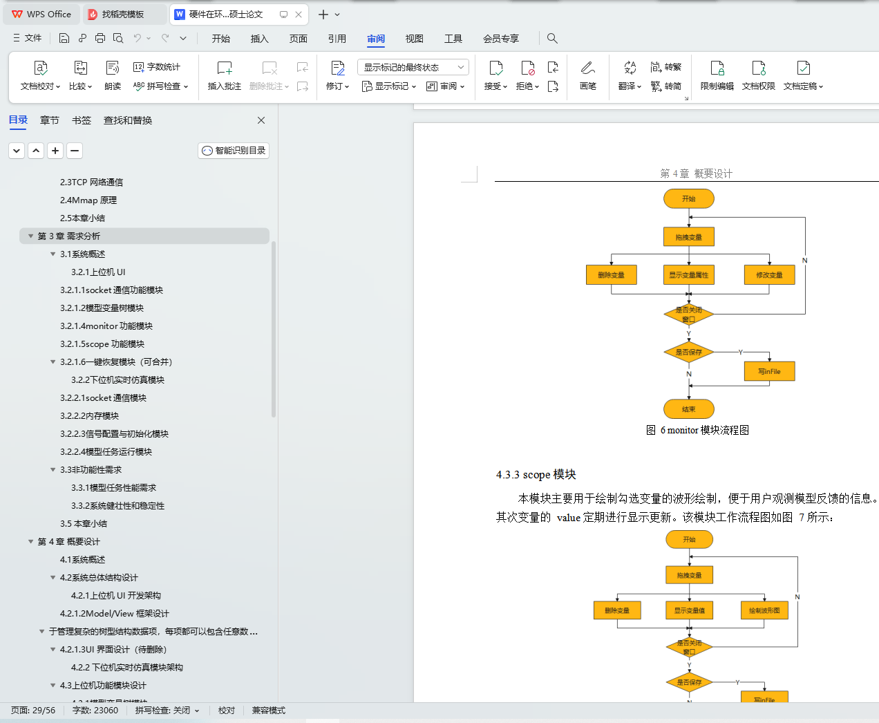
4.3.2monitor 模块 20
4.3.3scope 模块 21
4.3.4 恢复模块(上合 4.2.1.2) 21
4.4下位机功能模块设计 22
4.4.1共享内存模块 22
4.4.2信号配置与初始化模块 22
4.4.3模型任务运行模块 22
4.5上下位机通信设计 23
4.5.1通信协议设计 23
4.5.2TCP 客户端设计 24
4.5.3TCP 服务端设计 24
4.6本章小结25
第 5 章 详细设计与实现26
5.1上位机UI 功能模块的设计与实现 26
5.1.1Model 类的设计与实现 26
5.1.2TCP 客户端设计与实现 26
5.1.3变量树模块设计与实现 27
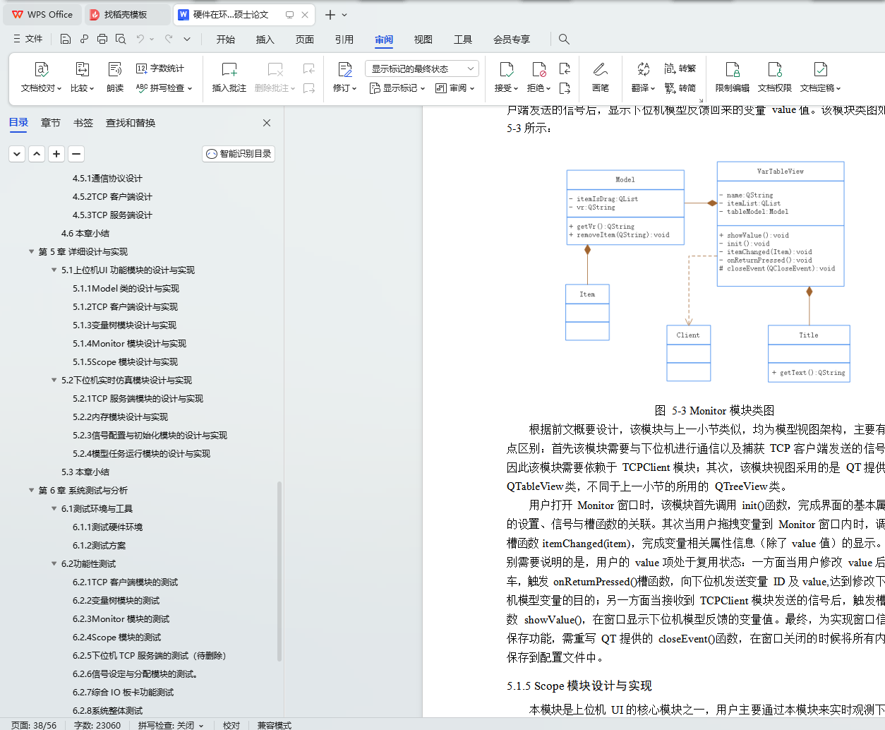
5.1.4Monitor 模块设计与实现 28
5.1.5Scope 模块设计与实现 29
5.2下位机实时仿真模块设计与实现 31
5.2.1TCP 服务端模块的设计与实现 31
5.2.2内存模块设计与实现 32
5.2.3信号配置与初始化模块的设计与实现 32
5.2.4模型任务运行模块的设计与实现 34
5.3本章小结 35
第 6 章 系统测试与分析36
6.1测试环境与工具 36
6.1.1测试硬件环境 36
6.1.2测试方案 36
6.2功能性测试 36
6.2.1TCP 客户端模块的测试 36
6.2.2变量树模块的测试 37
6.2.3Monitor 模块的测试 38
6.2.4Scope 模块的测试 39
6.2.5下位机 TCP 服务端的测试(待删除) 40
6.2.6信号设定与分配模块的测试。 40
6.2.7综合 IO 板卡功能测试 41
6.2.8系统整体测试 42
6.3非功能性测试 43
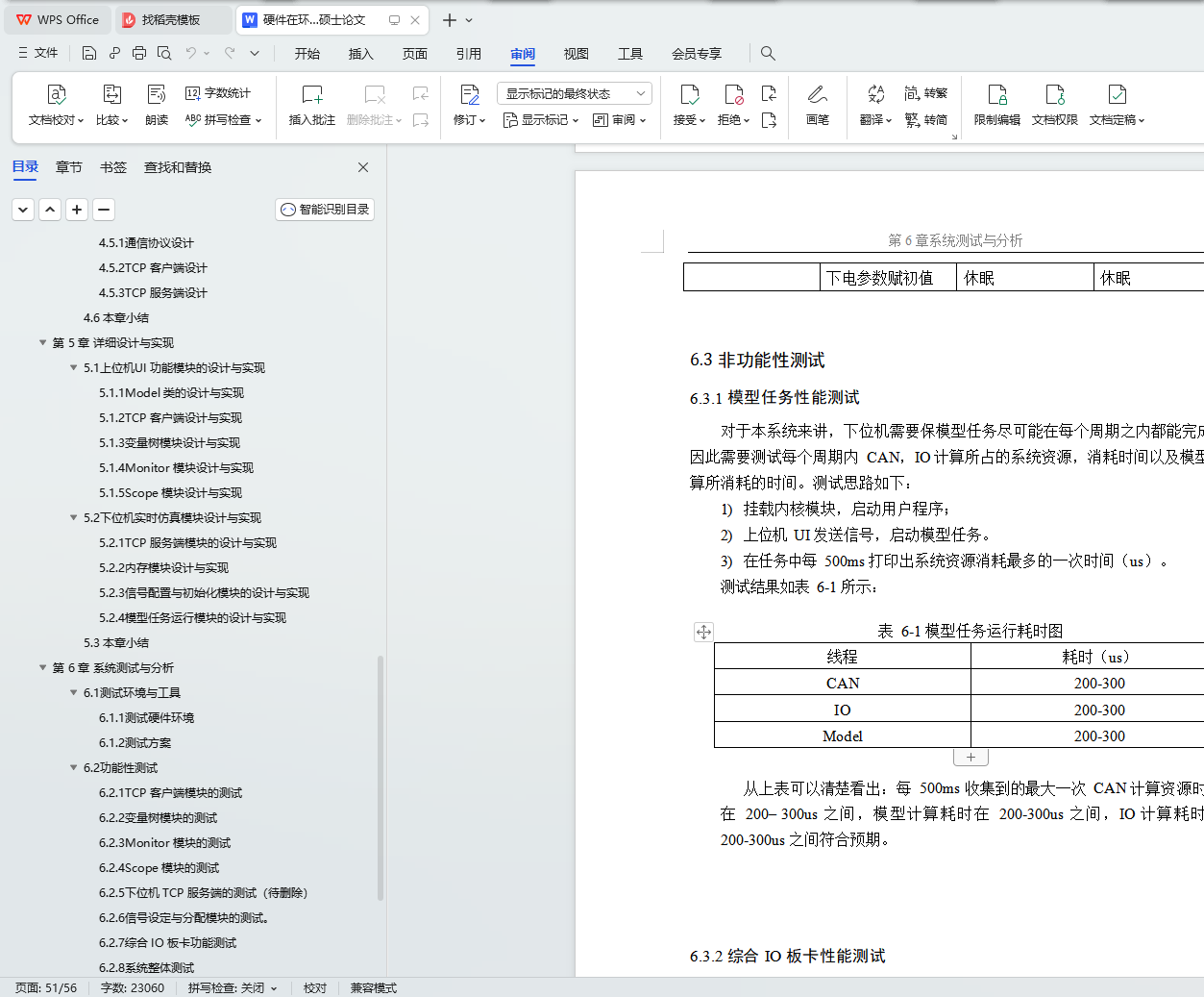
6.3.1模型任务性能测试 43
6.3.2综合 IO 板卡性能测试 43
6.4本章小结 44
第 7 章 总结与展望45
7.1 总结 45
7.2 展望 45
参考文献46
致 谢47
毕业66资料站 biye66.com ©2015-2026 版权所有 | 微信:15573586651 QQ:3903700237
本站毕业设计和毕业论文资料均属原创者所有,仅供学习交流之用,请勿转载并做其他非法用途.如有侵犯您的版权有损您的利益,请联系我们会立即改正或删除有关内容!